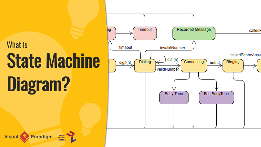
The State Machine Diagram models the behavior of a single object. It specifies the sequence of events the object goes through during its lifecycle. It also shows how the object responds to these events.
Why Use State Machine Diagrams?
State machine diagrams describe how an object’s behavior depends on its state. Responses to events change based on the state. These diagrams are commonly used for objects. However, they can also model other elements like actors, use cases, methods, or systems. State machine diagrams often pair well with interaction diagrams like sequence diagrams.
Note That:
- A state machine diagram shows all events, states, and transitions for a single object.
- A sequence diagram illustrates events for a single interaction across all objects involved.
Basic Concepts of State Machine Diagrams
States
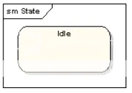
A state is shown as a rectangle with rounded corners. The name of the state is written inside.

Initial and Final States
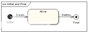
The Initial State is represented by a filled black circle and is labeled. The Final State is represented by a circle with a dot inside and can also be labeled.

Transitions
Transitions from one state to the next are represented by a line with an arrow. A transition can have a trigger, a guard (condition), and an effect (result), as shown in the following diagram.

Trigger is the cause of the transition, which can be a signal, event, condition change, or time. Guard is the condition that must be true for the trigger to initiate the transition. Effect is the action called directly by the object owning the state machine as a result of the transition.
State Actions
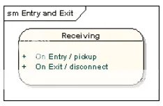
In the example above, the Effect is linked to the transition. If multiple transitions lead to the same target state, and each has the same effect, it’s better to link the impact to the target state rather than each transition. This can be done by defining an entry action for the state. The diagram below shows a state with entry and exit actions.

It can define actions that occur in response to events, or actions that always occur. It can define any number of actions of each type.
For more information, you can read this link: https://www.visual-paradigm.com/guide/uml-unified-modeling-language/what-is-state-machine-diagram/
Previous parts: https://ant.ncc.asia/wp-admin/post.php?post=16408&action=edit

