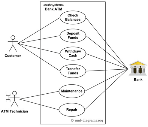
Now that we understand the symbols used in a Use Case Diagram, it’s time to assemble them to create a complete diagram.
Steps to Build a Use Case Diagram
Now that we understand the symbols used in a Use Case Diagram, let’s assemble them to create a complete diagram. Follow the steps outlined below:
Step 1: Identify the Actors
Begin by identifying the Actors in the system. To do this, answer the following questions:
- Who will use this system?
- Which systems interact with this system?

Example: ATM System
For instance:
- Who uses the system? → Customer, ATM Technician
- Which system interacts with this system? → Bank
From this analysis, we identify three Actors: Customer, ATM Technician, and Bank.
Step 2: Identify the Use Cases
After determining the Actors, analyze the functions they will use within the system. This step helps define the necessary Use Cases.
Example: ATM System
For example:
- The Customer uses functions like Check Balance, Deposit, Withdraw, Transfer.
- The ATM Technician performs Maintenance and Repair.
- The Bank interacts with all these functions.
In summary, the system requires the following Use Cases:
Check Balance, Deposit, Withdraw, Transfer, Maintenance, and Repair to effectively meet user needs.
Step 3: Identify the Relationships
Next, analyze the relationships between the elements:
- Define how Actors and Use Cases connect.
- Examine the relationships between Actors themselves and Use Cases themselves.
Once you establish these relationships, connect them to form a complete Use Case Diagram. This process ensures a clear and organized representation of system functionality.
Applications of Use Case Diagrams
Use Case Diagrams play a vital role in system analysis, design, and development. Here are some common applications:
- Analyze and understand the system.
- Design system functionality.
- Create a foundation for other diagrams, such as Class Diagrams, Activity Diagrams, Sequence Diagrams, and Component Diagrams.
- Facilitate communication with clients and stakeholders, which enhances collaboration.
- Support functional and acceptance testing by providing clear guidelines.
Conclusion
In conclusion, this discussion has covered the Use Case Diagram, a foundational tool in system design. As you continue practicing and applying these steps, you will build a deeper understanding of how to construct and use these diagrams effectively. This understanding will also support your work with related diagrams and processes in software development.
For more information, you can read this link: https://online.visual-paradigm.com/diagrams/tutorials/use-case-diagram-tutorial/
Previous parts: https://ant.ncc.asia/wp-admin/post.php?post=16408&action=edit


